About LCH Restoration

I restore and race Elden FF's. I solo and road race in vintage racing. I also have collected as much info on the Elden Marque as I can and work with Peter Hampsheir to further the official "Elden Registry" in the UK

Personal Elden Register

Since I bought my first two Elden’s I have taken allot of time to find other Elden owners. past or present.  I have collected that data by personal contact, open forums and referrals.

Peter Hampsheir maintains the Official Elden Registry and works very hard to preserve the history of the marque and wants to ensure no one creates new chassis without his knowledge.  I work hand in hand with Peter to keep track of mainly the US cars and share data with him regularly.

If you want to add info to this Elden Register, please contact through the site.  I will work with you to find the chassis # and correlate known history of the chassis to verify its authenticity in conjunction with Peter.  I would then request permission to add your car to both my personal register and Peter Hampsheir’s “Official Elden Registry”.  No personal data is included in this register and only be released with your permission.

In a few days I will provide a .pdf link to this register on this site after I update data just received.  Look back every so often for updates.

Larry

The question has come up on where to find the chassis #.  On most Elden’s it is on the rear bulkhead right side or maybe left.  Here is a picture of my chassis #:

MK10 Farme # annotated

Aligning the Elden FF tools etc.

My shop has a very non-level floor, 3/4″ drop in 8′ in various places  So I built some scale holders that have leveling feet.  Each leveling pad is made up of 1 1/2″ angle iron I had around the shop.  I welded a tube on each corner that is threaded for 3/8″ leveling pad.  One half of the assembly has 3/4″ plywood with 2″ high density foam as a resting pad when you want the car off the scales.  The other half is for the 15″x15″ scale pad which is used for all measurements.

I then laid out on the shop floor the wheelbase/track of the Elden and marked the floor for the leveling pads.  Took a large level and established level on the Left Front Scale Pad and projected that level across the other corners.  Put a small level on each pad and iterated leveling the pad to it’s self and its other pads until all pads are level to themselves and all others.  Marked floor for future use.

One issue I had as I began to use this setup pad was that each pad assembly would move each time the chassis was lifted, the camber change would move the pads sideways.  Also I didn’t have a good point to measure and set the ride height.  So I added a cross brace to the pads and that eliminated lateral movement and reliable place for ride height.  Not gorgeous but cheaper than a full setup pad.


I grew tired of trying to align the Elden’s with the various wheel/tire combinations I have.  So I decided to build my own wheel/hub stands..  Took a 1/2″ plate Al 6061, 3″ Aluminum 6061 angle and 4 casters to build my hub stands.


I drilled various holes to allow the wheel center line to move in 1/2″ increments to simulate the various wheel diameters I may encounter.  The hub stand eliminates the wheel/rim and sets on the scale pads.  This allows setting ride height, castor/camber and toe much easier. On the center line of the hub stand is a 12″ bar I use to establish toe of the wheel.

Another problem I had was trying to locate the chassis center line and setting the track at that center line. Once I found the center line by measuring many different points of the chassis pickup points and using the drawings found earlier.

Elden FF Chasis Drawing

Then made a permanent mark on the top chassis front/rear.  I then took a 6 ft level-attached a 6 ft tape measure on the top of the level, and installed a pointer on the level at 3ft to indicate the center line mark on the chassis.  I then spanned the level across the wheel/hub stands to measure the track.  Using plumb bobs at the end of the level equidistant from the center line, adjusted the a-arms. This is difficult on the front, as the a-arms have a very narrow range to use and I found a pickup point had been bent.  The rear this was much easier to establish.

For more details on how I make this all work please write me a note and I will try to elaborate more.


Feb 2018 Update

Morning to all,

Thought I would take a few minutes to catch up where we are in the winter work on the Elden’s,

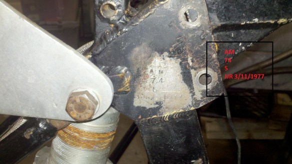
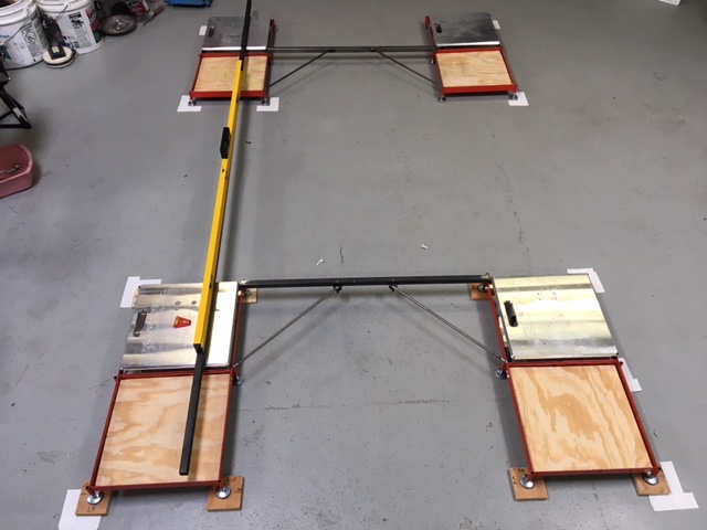
Elden #1,  AM 74-5,  is on the alignment rack, home made, to confirm last years setting and upgrade my measurement capabilities.  Below is a picture of my alignment setup.  My garage floor is not even close to flat, 3/4″ slope in 8′ in places.  So I took my Scale pads and built a pad holders with a roll off area behind the scale pad.

Shop alignment setup
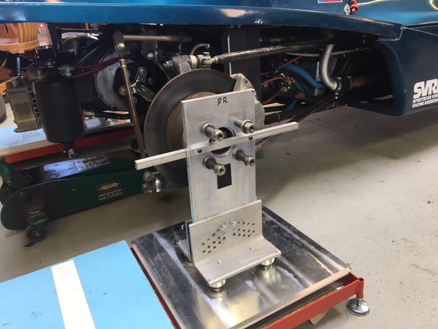
I also built my own hub stands to get the wheel assembly out of the way and allow a much more accurate surface to measure off of.

IMG_0948

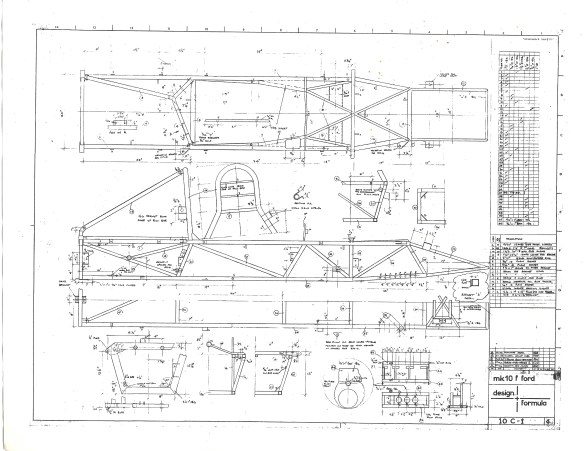
I also broke down and bought some Suspension Geometry Software to help me understand the Elden suspension design.  I have chased under-steer all of my time  with this car.  Some of the issue is my driving style and maybe the shocks are not in the correct range. (shocks were valved for a higher spring rate than we are using now).

After conversing with MK8 Motorsports in UK, https://www.mk8motorsport.com/, I have begun to follow their guidance on setup.  This required a softer spring package than I was using and maybe the pickup points on the lower a-arms was incorrect.  So with the software I hope to get some Roll Center numbers, camber change  etc.

The hard part of the suspension geometry software is accurately is inputting 3-D coordinates for all the pickup points.  So working on tools to aid in those measurements.


Elden #2, AM 73-39, was found to a have a severely bent frame. That frame in is Colorado Springs with Tom B. to straighten.  Hope to have back in late February.  Then we will start over building it with all clean, polished etc parts. This will take most of 2018.

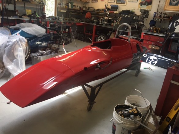
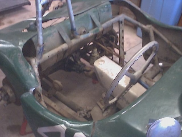
Elden #3, AM 73-79, has its new side radiators from Ron Davis Radiators in Phoenix, AZ.  It was a big challenged to plumb the radiator cross over piping and trying to ensure the driver is safe.  The radiator shrouds were from this car many years ago and were a challenge to fit.  Also with the cross over piping in the drivers compartment, the body parts and suspension are a bit more trouble to deal with than the front radiator cars.  So allot of planning and cussing takes place to fit everything.  I believe we are complete.

Next with Elden #3 is to  fit the front suspension, order shocks, etc.  The end maybe in sight!

Elden #4, AM 73-74, waits in the trailer for its time in the shop.  Unfortunately we have borrowed a few parts to further the other sisters completion.  One of the things we have had trouble with is front uprights.  In talking with MK8 Motorsports, they are now building Elden parts and have listings on their web site; https://www.mk8motorsport.com/elden-parts

I have sent them 3 damaged front uprights from my spares and they will attempt to repair or build new.  Give them a shout.

Will update the suspension work later.

Enjoy the Super Bowl Sunday!

Adding the Subaru Waterpump to Crosley Engine

Had seen others talk about swapping the original generator driven water pump with a 1980 Subaru Brat 1.6L pump.  That eliminates the generator which for an H-Mod isn’t entirely necessary.  On my engine I had scored a generator eliminator jack shaft.  But still wanted to eliminate the Crosley water pump.

I had seen instructions on the web and some preliminary drawings but until I started turning metal did I fully understand the process.

Parts List

1980 Subaru Brat 1.6L water pump Bech and Arnley #   Picture of pump

Champion 400A pulley- Tractor supply or most hardware stores

6 ea 6-32-1/2″ socket screws

5 ea 1/4-28-xxx hex head bolts and lock nuts/washers

3 ea 5/16-18-5/8″socket head or hex bolt/ washers

3″x2″-1/4″thickness-3 ” long Aluminum angle stock

First was to take the Champion 400A pulley and turn the center out of the pulley to allow its flat back face to attach to the front of the Subaru pulley front.

For my pump the diameter of the Champion 400A to fit the pump was 2.015″.  Faced the pulley to ensure flat mating surfaces.

Then Turned the back half of the Subaru water pump off to eliminate the unnecessary material.  I turned down to the pulley bottom.  Beware I turned this on the lath by holding the water pump body still, using dead center on the impeller shaft and turning off the pulley.  The pulley is cast steel and very soft in my situation.  “TAKE ALL SAFETY PRECAUTIONS”


Next determine a bolt circle on the inside of the “Champion 400A Modified” pulley and the Subaru pulley to allow 6ea 6-32 by 1/2″ socket head crews to be drilled thru the Champion 400 A pulley and taped into the modified Subaru pulley.  For my application that was 2.45″diameter.

Next fabricated from 4″x4″ by 1/4″ thick Aluminum plate a backing plate for the water pump.  For my application I used 1 1/4″ diameter tube as the outlet to the Crosley engine.


I haven’t finished this yet so decided to publish interim steps.  Will edit once installed into SIAM.

Larry

Elden Formula Ford MK10 Chassis Drawings

I want to share a set of drawings I received from John S.  John sent me  the MK10 chassis drawing, Lower A-Arms for Front and Rear Suspension and the Rear Hub casting.  Thank You John, for sharing these valuable pieces of information.

PS:  Elden spare suspension parts are available from MK Motorsports in the UK: https://www.mk8motorsport.com/

and GMT in the USA: http://www.gmtracing.com/

Note: GMT acquired the jigs for the Elden from Pat Price Engineering.

Note:  Just got this from Peter Hampsheir.

Larry,

The differences between the mk8 are minimal.

After 1981 the weight minimum was increased by 50 Kg to allow for mandatory for extinguisher. The Mk8 was already under weight and so I decided to put the exrta in the chassis for strength. The main members were increased from 1″ sq to 1 1/8″.

SCCA roll bar regs increased to 1 1/2″ dia. Rear radius rod mounts went to clevis mounting and the engine Y frame was made detachable. The rear cross-member was raised to permit inboard brakes.

The original  MK 8 chassis drawing was left on train and was superseded by the Mk 10 drawing 10C1 in Jan 74. This was the last mk10 chassis drawing.

Regards, Peter.


Elden FF Chasis Drawing

Elden Formula Ford MK10 Chassis

Elden FF front Suspension A Arm drawing

Elden Formula Ford MK10 Lower Front A-Arm

Elden FF Rear Suspension A Arm drawing

Elden Formula Ford Lower Rear A-Arm

Elden FF Rear Hub A Arm drawing

Elden Formula Ford Rear Hub

Elden MK 7 8 9 10 11 Rear bulkhead

Elden MK 7 8 9 10 11 Rear bulkhead


Indianapolis Baby!

June of this year year we entered the Falconer bodied Elden FF, AM74-5, in the SVRA Open Wheel World Challenge at the famed Indianapolis 500 Road Course.  I heard there were 350 open wheel cars entered and by looking at the drivers meeting in the media center I would believe it.  There were FV’s to F1 cars.  Pro series and amateur entrants.  I met a few folks driving F Jr’s from Australia and New Zealand.  Cool!

Here is a picture of me in “027” on the grid in Gasoline Alley.

IMG_0383

We came well prepared and had minimal problems with the car.  But when we left NM we knew that the under-steer in the car was still to be worked out.  We are running 300 lb/in springs front and rear.  We have been advised to go to 275 Fronts and 250 or softer in the rear. Upon getting home we will order those springs and see if it helps.  Note for History, Elden #4 AM73-74 springs were 225# front and 180# rears.  They appear to be original.  So during the races I fought some under-steer in the high speed corners.  So I took my time to ensure not to interfere with anyone of the faster guys.

Also I guessed at the gears and 4th was okay but 1-3 were to low and was unable to use effectively, so left allot of time on the table.  I was so consumed on trying to drive, I decided not to chase gears.  But I have a better idea from other competitors what should be in the Hewland for next time.

So here is a video of the last race.

Next race is High Plains Raceway end of July.


Larry


Update 7/4/2017 Elden FF 73-79

Well lets update the world.  We received a new a new body from Len at Marchant and Cox in the UK:

http://www.marchantandcox.co.uk/m-and-c-moulds

The Elden was originally a MK10 C which had the radiators mounted on the side of the chassis behind the front wheels.  So that is what we are restoring.  Steve C was working in the shop and began moving all the “bits” from Elden 73-39, the bent chassis, and began installing into this chassis.

Engine is a 4 hour old, iron head engine built by Pete Christensen in Fort Collins, Colorado at Total Precision Engines.  This engine had a brand new 711M block and Scat crank.

http://totalprecisionengines.com/PeteChristensen.php

The gearbox on this Elden was rebuilt by Taylor Race Engineering many years ago and never even had fluid put into it.

http://taylor-race.com/

So before Steve C could get to far along I decided we needed to mount the body as the side panels cannot be removed without removing the radiators and suspension.  Many of the mounting tabs had been removed in a past life, so I manufactured new ones.  The nose structure, holding the nose cone, had been removed and lost.  So with the luck of having Elden #4, an very original MK10C, was able to use its chassis to mimic the nose cone box.  One change will be the removal of the battery from the nose cone location to another place in the chassis.

Here is a picture of the nose cone structure from Elden MK10C 73-74:

IMG_1016

New nose cone support structure on 73-79

Now a picture of the body mounted to the car.

IMG_1024

Still need to design some Aluminum radiators that will fit the radiator shrouds and mount to the side panels.  Also I am building a 20 gauge Aluminum panels to mount to the side of the chassis to separate the water transfer tubes from the driver compartment.

So anyway the work continues.

Update May 2017

Well it has been a bit of time since I have updated this blog.  Since Oct last years we did our normal traveling in the fall and then spent most of the winter working on Elden AM74-5 and 73-39 and Am73-79

Elden 74-5 was found to have mismatched front uprights.  One was 1/2 ” taller offsetting the hub center line.  Borrowed 2 different ones from our last acquisition and began a search for new replacements.  Was introduced to 2 potential suppliers in the UK. One private individual and another a race shop:

https://www.mk8motorsport.com/

I also spoke to Pat Prince at Pat Prince  Engineering and he has the jigs for the suspension parts.  So soon I will be sending the stuff I need to Pat for repair or fabrication.

We are now running the new Hoosier VFF treaded tires a bit difference that the slicks I have run for years.  But we are nearing an optimum setup.

Elden #2 was nearing completion for this racing season.  Note I am doing preservation not restorations so I don’t strip down the car. When I picked up the car there was an invoice to “straighten the frame”.  Well it is still “bent”.  I couldn’t align the car, ran strings down the chassis found the rear sub frame tweaked 1/2″ at least.  So work has stopped.

Elden #3 AM-73-79 is getting a new body.  The old body had been cutup and missing some parts so I ordered a new body from:

http://www.marchantandcox.co.uk/m-and-c-moulds

New body

Hoping that body is here in June.  So the plan right now is to strip the bent chassis down for repair and to move forward on Elden AM 73-79.

Racing highlights:  We ran ran Elden 74-5 the MK10C rebodied Falconer and the video link is:

Well we will catch up again after the SVRA Open Wheel World Challenge at Indianapolis,  in June.


1954 SIAM Restoration Process-As Found

SIAM 100 Annotated

This picture was taken by Don Suiter in 1997 when he bought the car.  No work was done until 2004.

00060017

Note that the rear firewall is just a canvas cover.  The rules sure have changed over the years.

SAIM 120 annotated

0019

What was interesting on the SIAM when I got it was all the interior gearbox covers and driveshaft aluminum covers were 20 gauge metal loosely placed into position.


Rear canvas "firewall" removed exposing the ladder frame, roll bar, gas tank. Let me ask you: Trust that roll bar? Rear “firewall” canvas removed exposing roll bar structure, really?

Crosley engine Label1950’s Crosley engine, 750 cc, twin 32 PBIC Carbs, custom camshaft and 4 to 1 custom exhaust header.


Elden Build History from “RACECAR” May 1979

I was looking back at some old files and found this article from “RACECAR” from May 1979″.

This link is to the whole article describing Formula Fords built from the mid-60’s to 1979.

Charting the Fords-FF general info

What is most interesting to me is the Elden Formula Ford part of the article.  The following link is the only place I have seen the where the 4 models of the PH10 are described relative to the radiator placements:

1972-73 PH10 with single front radiator similar to the PH8

1973   PH10A is a PH10 with the “Falconer” body with twin front radiators.

1974   PH10B is a twin side radiator layout with the radiators directly behind the front suspension

1975   PH10C is a twin side radiator layout with the radiators moved alongside the roll hoop

Elden Registry info

In talking with Peter Hampsheir he indicated that many of the PH10B and C’s were converted to the front radiator design (PH8 and 10).  But what I am listing here is just some info I don’t want to lose.  If anyone has more info please share your info.